Figure 1 - Dipole Voltage and Current Distribution
On this page I will try and describe what I know about End Fed Half Wave Length Antennas. I am always learning so you may see this page change from time to time as I learn more and correct errors. I don't expect anyone to take this information as gospel. I just hope that it helps others successfully use this type of antenna since it does have some unique advantages.
An End Fed Half Wave Length Antenna is a variation of the much more common half wave length dipole antenna. When an antenna that is one half wave length long has RF energy applied to it at its resonant frequency a standing wave develops on it. This standing wave consists of both current and voltage that are 90 degrees out of phase. The end result is a distribution of current that is at a maximum at the center and a distribution of voltage that is at a maximum at the ends (fig.1).
Figure 1 - Dipole Voltage and Current Distribution
The most common method of feeding energy to this type of antenna is at the center where the current is maximum and the voltage is minimum. Consequently, the impedance at this point is low and on the order of 72 ohms. This makes it convenient to feed the antenna directly with low impedance 50 ohm coax cable. To minimize the chance of common mode currents on the coax that can cause the coax to become part of the antenna a balun is sometimes used. Feeding the antenna at the center is by no means a requirement however. Energy can be fed anywhere along its length and the impedance will increase as the feed point moves away from the center (more voltage, less current). Taking this to the extreme is to feed the half wavelength antenna at its end. At first thought this would seem to be impossible yet many people have done it very successfully. In practice the impedance at the end of an end fed half wavelength antenna is on the order of 1800 to 5000 ohms.
It is often commented that the End Fed Half Wavelength Antenna needs no "counterpoise" or radials to work. In practice this type of antenna is often used in the field with no "counterpoise" and it performs well. In reality something is always being used as a "counterpoise" even though it may not be evident at first glance. There have been many heated arguments between folks who really only differed in whether they sided with the practical aspects of using this antenna or the sterile theoretical description of the antenna (fig. 2).
Figure 2 - Theoretically Will Not Work
Since myself and others have been very successful at doing the seemingly "impossible", I will attempt to describe what I think is going on. Even though there should be no limitation as to what frequency this antenna can be used on my discussion here is mainly related to HF since this is where this type of antenna is most practical. Also, keep in mind that I usually use this antenna at low power levels (<20W). There are high voltage issues to take into consideration when using higher power levels, mainly with the capacitor in the tuned LC circuit. Don't try to run 1.5kW through a tiny coupler using polyvaricons! There are some distinct advantages to using QRP. With proper component scaling high power can be used. I have successfully used 100W without any problems with this coupler. For permanent home use you may also want to try a conventional L-network consisting of an inductor in series and a capacitor to ground on the antenna side. The L-network does not offer the feedline isolation that a link coupled tuned network does but it does offer a larger bandwidth for a given setting.
Hams have been successful end-feeding resonant half wavelength antennas for decades. Typically, a parallel tuned circuit is used at the end of the antenna with the feed line link coupled or tapped to the coil in the circuit. I found empirically that the impedance of this antenna is about 1800 to 5000 ohms when things are adjusted properly. Antenna modeling suggests that the impedance is closer to 1800 ohms depending on the "counterpoise" length used. As the "counterpoise" itself approaches a half wavelength, the impedance approaches 5000 ohms. In the graph below I have plotted what MININEC predicts for the impedance of an end fed half wave antenna versus the "counterpoise" length. The antenna's length (approx. 0.47 free space wavelength) was determined by modeling the length required to obtain resonance (jX = 0) when the "counterpoise" was the same length. In other words, it was modeled as two half wavelength wires end-to-end and the length of each was kept the same but adjusted to obtain a purely resistive match.
Figure 3 - Impedance versus "Counterpoise" Length for an End Fed Half Wave Free Space Antenna
Figure 4 - Two Half Wave Length Conductors End-To-End for Determining Resonance in Modeling
In figure 3, particular attention to the points where the impedance is purely resistive (jX = 0 ohms) at 0.05 wavelengths and about 0.47 wavelengths. The 0.05 wavelength "counterpoise" length is what I also determined empirically as to being the ideal length for the counterpoise. The coupler can be adjusted to compensate for any reactance that may be present due to other lengths but it is around this length where the whole antenna system is the most stable and provides a purely resistive load to the coupler. Notice that there is nothing magical about the often recommended 1/4 wavelength "counterpoise" with this antenna!
Below is the ideal setup for an end-fed half wavelength antenna that I have determined through experiments and antenna modeling (fig. 5).
Figure 5 - Ideal End Fed Half Wave Length Antenna
The exact impedance of an end fed half wave length antenna has been debated but if you design a coupler to match close to the impedance range in figure 3 a good match can be obtained. Some hams have had great success with this antenna with no feed line imbalance problems (common mode currents) while others have had very bad "RF in the shack" problems due to the feed line radiating as much as the antenna. If you adjust your coupler into a resistive load on the bench first and then adjust the antenna for a proper match then you should have a resistive match that will minimize current through the coupler and through the "counterpoise".
When you design a coupler for this antenna it helps to know what turns ratio you should use. Use the formula below to determine the turn ratio. Based on the predictions above a 6:1 to 8:1 turns ratio will be close enough. I have often used a 10:1 ratio with acceptable results. The exact ratio will probably be a function of the inductance value that you need on the secondary to obtain resonance in the frequency range desired with the capacitor that you have available.
Za = antenna's resistive impedance
then,
Turns Ratio = √(Za/50)
For example:
6:1 for Za = 1800 ohms
7:1 for Za = 2450 ohms
8:1 for Za = 3200 ohms
9:1 for Za = 4050 ohms
10:1 for Za = 5000 ohms
If you look at the predictions below (fig. 6) you will see that a ratio of 8:1 provides the most stable SWR versus "counterpoise" length. This is assuming direct transformation of the antenna's complex impedance to 50 ohms. In reality, most couplers will be able to tune out the reactance to achieve a much lower SWR but you should try to operate at the point where the antenna's load is resistive, especially if the feed line and coupler are the "counterpoise" as in figure 15. In circuits where the feedline is physically isolated (link coupled, fig. 5) there doesn't seem to be much of an issue. The only reason that I suggest adjusting the antenna so that it provides a resistive match is because I believe that is the point at which the current through the coupler will be at a minimum and therefore the least amount of return wire ("counterpoise") is needed to complete the circuit.
Figure 6 - SWR vs "Counterpoise" Length vs Turns Ratio for an End Fed Half Wave Free Space Antenna
The graph below (fig. 7) is of actual measured data of an end fed half wavelength antenna with an isolated coupler using an 8:1 turns ratio. The coupler was tuned to resonance on the bench first using a resistive load. Although not exactly the same, you can see that the data resembles the predicted (red) data in the graph above (fig. 6), especially for the shorter "counterpoise" lengths. I suspect that the difference in data is due to the fact that the predicted data was for a free space antenna and the measured data was for a real antenna at a low height in a relatively cluttered environment.
Figure 7 - Measured SWR vs "Counterpoise" Length vs Turns Ratio Data for an End Fed Half Wave Antenna
Keep in mind that even in the real measurement above the SWR could have been brought down to 1:1 in most circumstances by simply adjusting the coupler's tuned circuit and/or turns ratio but the idea is to show the result when the coupler is fixed tuned at the bench first. With higher antennas I almost always achieve a 1:1 SWR without retuning the coupler.
According to Moxon [1], because of the very high impedance (i.e., very low current) at the end of a half wavelength antenna, only a small counterpoise (1m @ 14 MHz) or a few pF of capacitance to ground is required to return the current. However, in order to maintain a balance an equal amount of length is required to be added to the antenna itself. So even though the antenna is fed at the end, a good balance is maintained. Below (fig. 8) is what I understand Moxon [1] tries to describe.
Figure 8 - Moxon's Ideal End Fed Half Wave Length Antenna (with a bit added by AA5TB)
In the above diagram you can see that the half wave portion of the antenna presents very high impedance to the 0.05 wavelength section added and free space presents very high impedance to the other end of the 0.05 wavelength "counterpoise". Therefore the center fed portion between the two 0.05 wavelength sections is essentially balanced. With no physical connection to the feed line common mode currents along the outside of the feed line will be at a minimum. The main potential path for imbalance will be through capacitance to the surrounding environment, just as is the case with any dipole. Notice that the antenna is no longer a resonant length.
At first I agreed with Moxon because it made sense and my usual couplers could easily tune out the reactance in the load. For a link coupled antenna this would all work fine. However, I now believe that the way to minimize common mode current in circuits where the feedline may not be totally isolated is to use a resonant half wave length antenna adjusted to provide a resistive load to the coupler. If this is done then the current into any length of "counterpoise" is minimal except when those lengths approach a half wave length. If the current is minimized on the "counterpoise", then potential common mode problems are minimized too.
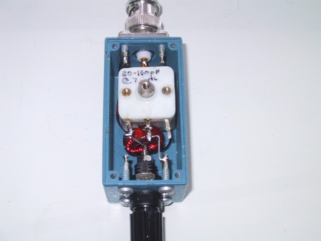
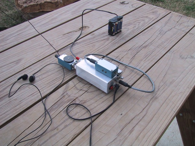
Below are some photos of an experimental setup for 20m that helped me understand what is going on with end fed half wavelength antennas. I first adjusted the LC circuit using a 4.7k Ohm resistor (fig. 9) in the CW portion of 20m to obtain a 50 Ohm match using my MFJ-259B Antenna Analyzer. When the antenna was properly installed I adjusted its length along with a 1m long counterpoise to obtain the same 50 Ohm resistive impedance without having to retune the circuit (fig. 10). At this point the antenna worked well. I then removed the 1m long counterpoise and I was no longer able to obtain a match at any setting (fig. 11). Essentially, the antenna was not energized. I had taken measures to prevent as much coupling as I could to the shield of the coax (no direct connection, fig. 12, and ran the coax 90 degrees to the antenna). There may have been some stray capacitance but there was not enough to "complete the circuit". It should be noted that increasing the counterpoise beyond 1m made no noticeable improvement. Also, if this method of adjusting the tuned circuit (using resistor first) is not used then any deviation from the optimum antenna length will cause an increase in return currents in the "counterpoise" making the "counterpoise" requirement more critical. I believe this accounts for some of the failures that have been described in ham reports that were supposedly corrected when a 1/4 wavelength radial was added. Any deviation from the resonant antenna length will require a similar increase in "counterpoise" requirement. This is not to say that the antenna cannot be used at other frequencies. If you do plan on operating over a large range of frequencies then the "counterpoise" requirement increases but a match can usually still be obtained by retuning the coupling circuit.
Figure 9 - The Proper Method of Tuning an End Fed Half Wave Length Coupler
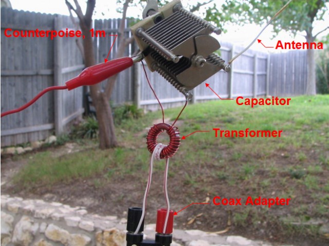
Figure 10 - Proper Feed - 1m return (counterpoise).

Figure 11 - Improper Feed - No counterpoise at all, no worky.
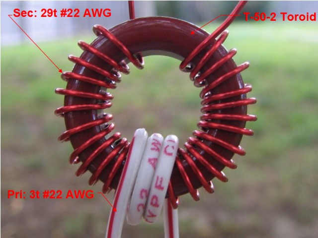
Figure 12 - Close-up of Transformer (Typo Note: The torroid is actually larger than a T-50-2)
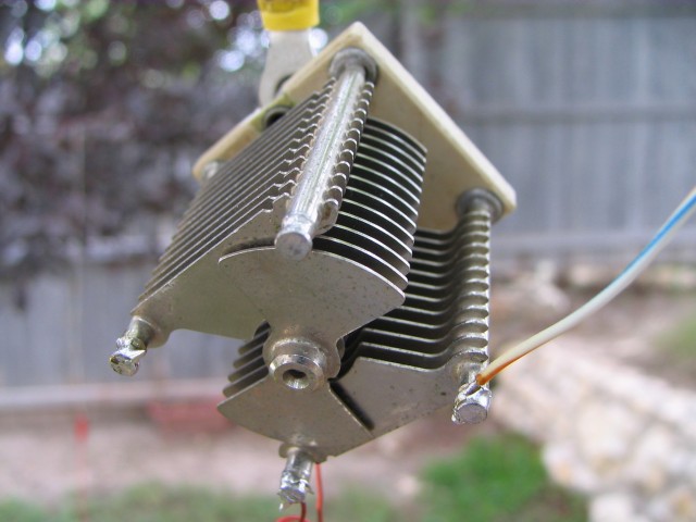
Figure 13 - Close-up of Capacitor
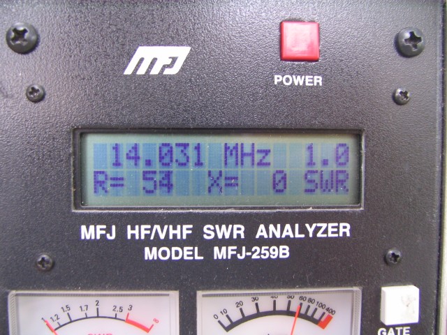
Figure 14 - Match when properly adjusted with 1m counterpoise
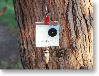
In many configurations of the end fed half wave antenna a counterpoise is not used at all. So how is this possible? The test above proved that this is not possible. However, in the real world it is possible to connect the return side of the LC circuit to the ground side of the feed line as shown below (fig. 15). Even though no apparent "counterpoise" is connected the feedline and/or rig is actually used as the "counterpoise". This is often my arrangement for field work.
Figure 15 - Return via Coax and Rig
In some cases simply the stray capacitance of the LC circuit to the environment and feed system will provide enough counterpoise as shown here (fig. 16).
Figure 16 - Return via Stray Capacitance to Environment and Feedline
Obviously the above two configurations appear to have the potential for the dreaded common mode currents if some sort of choke balun is not used. However, due to the very high impedances involved currents levels are very low when the antenna is of the proper length and when the LC circuit is adjusted properly decreasing common mode currents. Given that the impedance is high designing a choke balun with enough impedance to be effective may be difficult anyway. However, if this setup is being used in the field with very short or no coax (direct attachment to rig) then any common mode currents that do exist will be negligible. Only when the "counterpoise" (and/or feed line common mode path) becomes near a half wave length itself will the return currents equal that of the antenna. Another possible problem scenario could be when the antenna is fed through a 1/4 wavelength of coax to a grounded rig. In most field setups where I use this type of antenna neither of these two cases occurs. It should be noted that in these cases adding the often recommended 1/4 wavelength radial will not necessarily alleviate the problem either. The 1/4 wavelength radial recommendation often given is based on the assumption that a high impedance at the open end of the "counterpoise" will present a very low impedance at the return side of the coupler. This is indeed true but not required. Remember, the impedance is relatively high at this point so a very short "counterpoise" is all that is required. A longer "counterpoise" offers nothing to the performance and this can be verified by computer modeling. If the coupler and end fed half wave antenna are properly adjusted then you should have no problems using a very short "counterpoise" or depending on stray capacitance for the return.
So far this discussion has had the antenna floating in space for the most part. Down at earth it can be used in any configuration that an ordinary center fed dipole can be used. One common orientation is vertical. In this case many people say that a large radial system consisting of up to 120 radials are required just as is required for a 1/4 wavelength vertical (see below). As far as completing the half wavelength antenna is concerned there is no difference between vertical and horizontal orientation! No radials are required. However, an improvement of the ground system below ANY antenna (except maybe a Beverage antenna) will help its overall performance. The closer any antenna gets to the ground the more current is induced into that lossy ground. Any improvement that you make to this lossy ground will improve this situation. There is just no need to unduly require it to "complete" a half wave length vertical, whether fed at the end or anywhere else. Once again the "counterpoise" requirements are the same as above. There have been many manufactures over the years that built half wave vertical antennas that had only a few short radials. For VHF, anyone who has ever used the old AEA Hot Rod end fed half wave antenna for an HT know the drastic improvement it made over a 1/4 wave antenna.
Here are some other examples of the end fed half wave antenna. The LC lumped component tuned circuit described above can be replaced by a 1/4 wave length of shorted transmission line (stub) as shown below (fig. 17).
Figure 17 - Lumped LC Circuit Replaced with 1/4 Wave length Stub (End Fed Zepp)
If you take this a few steps further you can see how the antenna evolves into a classical J-Pole antenna that is often used at VHF with good success (fig. 18). This shows the general idea anyway. N3GO has a much more detailed description of the J-Pole antenna here.
Figure 18 - J-Pole Antenna
There are many ways to configure an end fed half wave length antenna. Another very effective DX antenna is a ground mounted half wave length vertical antenna as shown below (fig. 19). A single ground rod will often suffice for a ground system to complete the circuit since very little current has to flow through this ground system.
Figure 19 - Ground Mounted Vertical Half Wave Length Antenna
The graph below (fig. 20) gives an example of the feed point impedance of a vertical monopole versus its height in terms of wave length. The ground plane is assumed to be perfectly electrically conducting (PEC). Notice the points where jX = 0 ohms. These are the points where the antenna is resonant, at 0.25 wave lengths, 0.47 wave lengths, and again at 0.74 wave lengths. The main difference between the points is the impedance. For a height of 0.25 wave lengths the resistive impedance is about 35 ohms and a height of 0.5 wave lengths it is about 2450 ohms.
Figure 20
If you design a coupler to feed an impedance of 2450 ohms (7:1 turns ratio), then the expected SWR for a vertical monopole operated against ground is shown below (fig. 21). Note that a perfect match occurs when the vertical is about 0.47 wave lengths tall.
Figure 21
Here are my thoughts (right or wrong) about ground losses with end fed half wave vertical antennas. Let's say you just use a ground rod for a return. To return the displacement currents that enter the ground from the field around the antenna there will be a high earth resistance with such a simple ground. Let's use 35 Ohms for an example. For the 1/4 wave length vertical with 35 Ohms of feed point resistance, the input power will be divided between the ground resistance and the feed point resistance. The two resistances will add up to a total feed point resistance of 70 Ohms but the efficiency of the system will only be 50%. For the 1/2 wave length vertical with an assumed feed point resistance of 2450 Ohms the feed point resistance will be 2485 Ohms (2450 + 35) and the power dissipated in the earth at the feed point will only be 1.4%. This gives us an efficiency of 98.6% for the 1/2 wave length vertical. With an efficiency of 98.6% I don't see any reason to lay down an elaborate radial system for a 1/2 wave length vertical from an efficiency point of view. However, at about a 1/4 wave length from the base of a 1/2 wave length vertical the ground currents once again increase. Of course this pattern will repeat itself out for many wave lengths from the antenna. For this reason a bunch of (>1/2 wave length) radials should make an improvement on ground wave field strengths or on very low elevation sky wave paths by lowering the pseudo-Brewster angle. However, I am skeptical about how much of these ground (or surface) wave currents, if any, return back to the feed point and contribute to the feed point losses. In any case, to reiterate my earlier statement, improving the ground conductivity out for many wavelengths will improve the far field of any antenna, at least at some elevations. This does not mean that an elaborate ground is required for an end fed half wave length vertical antenna to "have something for the antenna to push against" or to "complete the circuit" as is often said. Whether or not you consider ground loss several wave lengths from the antenna as antenna system loss or not is up to you.
I hope that I have shown that feeding a half wave length antenna on its end without an extensive ground system or "counterpoise" is practical and it really works. I use this type of antenna extensively in the field with my little single band QRP rigs. For example, I have found that my 20m vertical end fed half wave antenna with the bottom 1m from the ground is an extremely effective antenna. During Field Day activities I can usually rack up 500 contacts using only 4 or 5 Watts. DX is very easy with this arrangement as well. Give it a try!
[1] HF Antennas for All Locations, L.A. Moxon, RSGB, 1990, pgs. 43,46.