A balun is a device that is used at the feed point of a balanced antenna when an unbalanced feed line is desired to feed the antenna. Balun is a contraction for BALanced to UNbalanced. A common example of where a balun would be desired is at the feed point of a dipole antenna when a coaxial transmission line is used. If a balun is not used it is possible for common mode currents to be present on the feed line. The effect of this could be undesirable if the directional properties of the balanced antenna are to be maintained. Since the feed line usually leads into the shack RF could be present in the shack to create RFI as well as the possibility of receiving excessive amounts of RFI from indoor noise sources. It is often found that a balun is not necessary and everything works just fine feeding the balanced antenna directly with coax cable. When this is possible it may be found that the feed line is an odd multiple of 1/4 wavelength. In this case the transmitter end of the feed line is usually grounded and up from this point on the coax 1/4 wavelength or a multiple thereof will appear as a high impedance. When this high impedance point occurs at the feed point chances of common mode currents are low. Rather then take any chances it is often recommended to use a balun.
There are several different kinds of baluns. Some provide a 1:1 impedance ratio while others can provide 1:1.5, 1:4, and many other impedance ratios. A 1:4 ratio balun would come in handy if you were feeding a folded dipole (200 Ohms) with 50 Ohms coax. For a 1:1 ratio a balun can be constructed using the feed line itself by simply winding about five turns of the feed line around a 2" diameter piece of PVC. I preferred a 1:1 ratio balun that I could easily move from one antenna to another by simply unscrewing the coax.
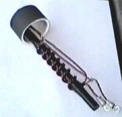
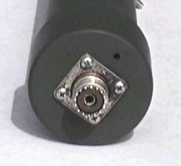
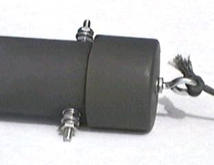
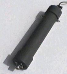
My balun uses AWG 12 enameled wire trifilar wound on a 6" X 1/2" piece of ferrite rod. 7 turns are tightly wound around the electrical tape covered rod. The free ends of the windings are connected as shown below in the schematic. The whole balun is installed in a 10" piece of 1-1/2" schedule 40 PVC pipe. A SO-239 coaxial connector is installed in the bottom end cap with #4 stainless steel hardware. An eyebolt is installed in the top end cap. The antenna post consist of #10 stainless steel hardware mounted on opposite sides near the top of the PVC pipe.
First I drilled all of the necessary holes, including a drain hole in the bottom end cap, and then painted all of the PVC pieces with olive drab paint the protect from the elements. Next the balun was connected to the SO-239 connector and then the pipe was slid over the balun and cemented in place with PVC cement. At this point the balun was connected to the antenna binding posts. Then the top end cap was installed with PVC cement. I tested the balun by attaching a 50 Ohms termination to the antenna posts and my MFJ-259B via coax to the coax connector on the bottom. The 50 Ohms resistive impedance was reflected back through the balun with little reactance throughout the HF spectrum. Since the design was based upon a tried and true design I am confident that it performs as expected as far as choking off currents.
I found this balun really easy to build and should easily handle a large amount of RF power as long as the SWR of the antenna remains low. A purchased balun may only cost a little more then my homemade version but I had the parts on hand and it was fun to build.