Over the years many hams have e-mailed me asking how to construct an end fed coupler for 100W or more. I didn't think it would be hard but I had not actually constructed one before. Hopefully my experience with this coupler will help them design theirs.
In June of 2007 I decided to build an end fed half wave coupler that would handle the full power of my Drake T-4XB transmitter. I was using my inverted-L antenna that was 1/2 wave length on 40m and 1 wave length on 20m. I designed this coupler so that there was no physical connection between the coupler and the coax cable. I used my ground rod as the only return ("counterpoise") and link coupled the transmission line as shown below. I would advice installing some sort of spark gap from the antenna to ground to provide a path for lightning energy. The coil in the circuit already provides a DC path for static charges but you need a low impedance path for lightning. I still need to do this!
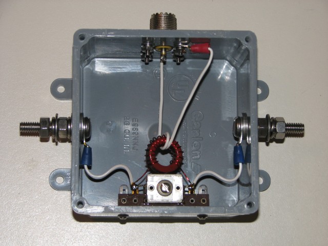
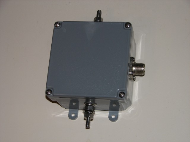
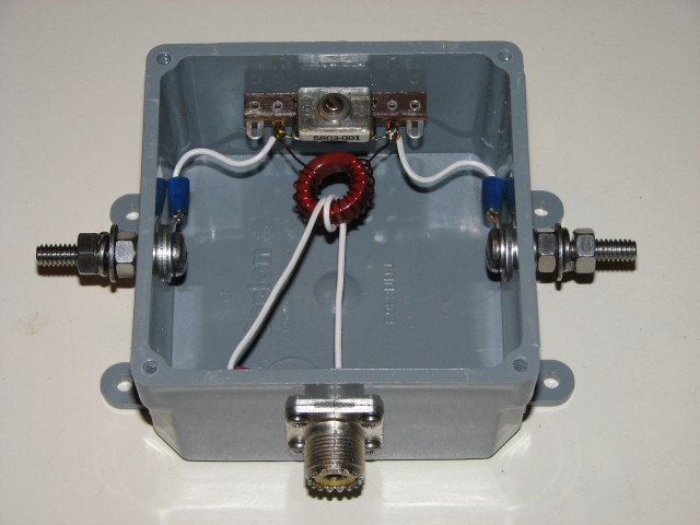
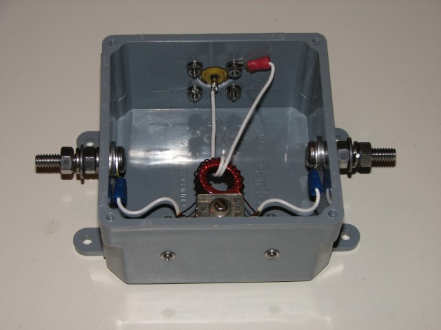
I built the circuit into a plastic and waterproof electrical box that I had purchased at The Home Depot. The box is made by Carlon and is 26 cubic inches in size. I used 1/4" stainless steel hardware for the antenna and ground connections and a small terminal strip to mount the components. As you can see in the photo I used a small T-80-2 powered-iron core with 2 turns of 22 AWG bell wire on the primary and 17 turns of 22 AWG enameled wire on the secondary. The capacitor that I used was a compression trimmer that I picked experimentally by checking to see which one of my junk box capacitors would resonate the circuit on the bands that I wanted. The 17:2 turns ratio was selected by adjusting the secondary number of turns to enable the capacitor to resonate the circuit on both 40m and 20m (one at a time) and the 2 turn primary was selected as the best value to provide a decent match to a 4.7k ohm resistor. This circuit would provide a near perfect match to about 3600 ohms but given the high impedance loads expected with this type of antenna I don't expect more then about a 1.3:1 VSWR at resonance. Ideally one would try for a 7:1 to 10:1 turns ratio in this circuit but the available capacitance range is usually the limiting factor on the exact turns ratio that you can come up with. In practice the turns ratio isn't very critical as long as you don't expect a perfect 1:1 VSWR. The turns ratio can deviate up to +/-20% from the ideal ratio in this circuit and still provide a 1.5:1 VSWR or less.
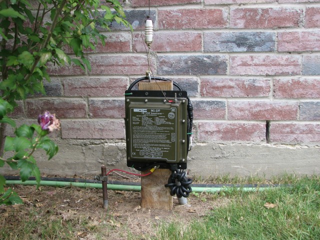
In the beginning of June I removed my SGC SG-237 autotuner and put this coupler in line. It worked very well on both bands (one at a time) until it rained! Somehow water was seeping into my coupler and getting the capacitor wet. I put it back on the bench and removed all of the components that protruded through the box. I then put RTV silicone on all of the threads and washer surfaces. Since then I've had no more water problems.
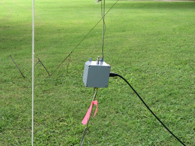
For Field Day 2007 I operated with my local club and they decided to run QRO this year. I brought out this coupler and used it with an end fed half wave vertical antenna for 20m. I used a 2' long wire braid and a 1' long stake in the ground to create about 3' (1m) of return ("counterpoise").
The antenna worked fantastic! About 500-600 QSOs were made on just 20m and I had pile-ups of stations coming back to me. I've used this type of antenna on Field Day many times so I wasn't surprised by the performance but this was the first time that I've ever run 100W for 24 hours through a little coupler like this. I am happy to say that there were no signs of heating, drifting, or voltage flashovers. As usual, there was the added bonus of some very good band pass filtering due to the tuned circuit of the coupler which helped to prevent other stations in the area from causing interference.
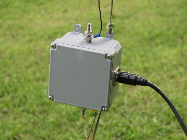
Here are some more photos of this coupler: