Schematic of the T-Monopole Antenna
Schematic of the T-Monopole Antenna
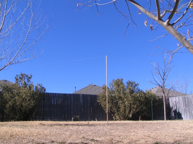
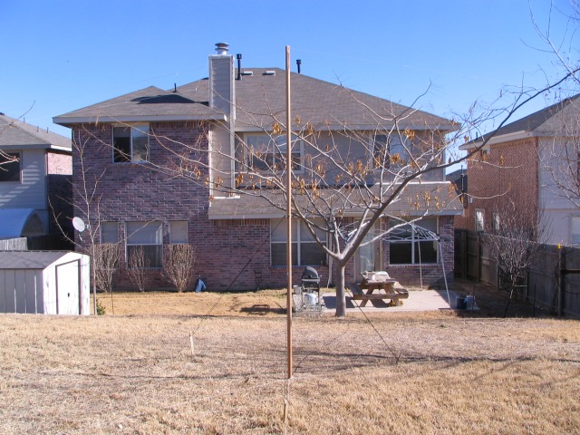
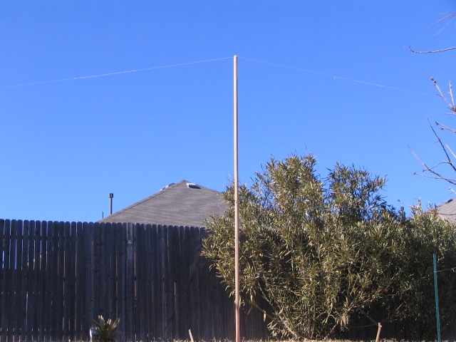
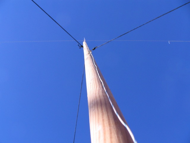
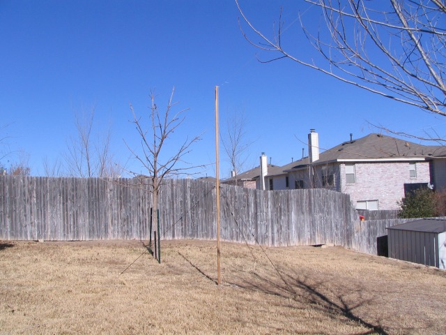
During the very warm and extremely dry start to 2006 I thought it would be a good time to do some antenna experimenting. I wanted to see how well a ground mounted vertical monopole would work on 20m in my small city sized lot. The tallest vertical support that I had available at the time was a 10 foot long wooden pole. Since this is too short for a full 1/4 wavelength vertical for 20m I decided I would try top loading the antenna to make it resonant. I modeled a T type configuration where the 10 foot vertical section was top loaded with a horizontal wire. This essentially creates a capacitive top hat the contributes very little to the radiation pattern due to the phase distribution in this top section yet provides the most efficient form of loading. Since I wouldn't be mowing my dead yard for a long time I knew I could lay out some radials and do a proper installation (electrically).
Modeling indicated that the antenna should perform almost well as a full size 1/4 wavelength vertical but with a slightly lower feed point impedance (24.3 + j6.2 ohms).
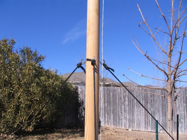
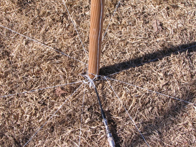
I spent a day constructing the antenna. As you can see from the photos below I attached hooks to the pole for the guy ropes and for attaching the antenna wires. The antenna was constructed from Teflon coated silver AWG 22 wire. I laid out nine 3m radials and stapled them to the ground using ground staples. The top T section was tied off to my wooden fence using string.
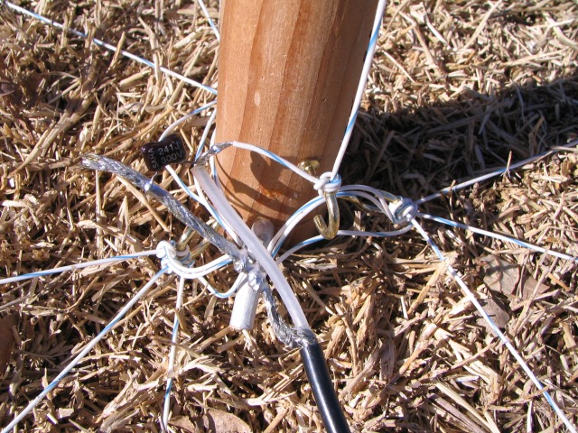
I used 3 hooks at the bottom of the pole to use as attachment points for the radials. I attached the 9 radials as shown below.
Measurements with my MFJ-249B Antenna Analyzer confirmed that the feed point impedance was very close to the predicted 24.3 + j6.2 ohms. Experimentally I found that a 240 pF capacitor across the capacitor converted to feed point impedance to 50 ohms (1:1 VSWR). Later I used my antenna modeling software to calculate what would be required to match the antenna and calculated a value (233.2 pF with 0.21 µH series inductance), very close to what I had found imperially.
Modeled Feed point Impedance & Matching Section
I soldered a 240 pF silver mica capacitor across the feed point as you can see in the photo below:
With the 9 radials that I used the antenna was modeled to have a nice pattern with a peak in gain at 29.7 degrees. The addition of many more radials should lower the angle of radiation somewhat by filling in the lower elevations. The predicted pattern in shown below.
T-Monopole 2D Patterns
T-Monopole 3D Pattern
The performance of this antenna appeared to be consistent with the predicted patterns. I did perform A/B comparisons with this antenna against a horizontal dipole. Given the tight environment that the two antennas were in the performance between the two antennas were very similar with exception of polarization differences and directions in which the dipole antenna had nulls in its pattern. Overall the T-Monopole antenna would make an easy antenna to disguise for an HOA infected neighborhood and still have a good, predictable pattern.